User Tools
Sidebar
Table of Contents
User Coordinate System
The User Coordinate system tools are found under 'Home > User Coordinate System'.
Manual UCS
 Creates a Project UCS my entering numbers manually.
1. Begin by clicking the 'Manual UCS' icon  to open the 'Create Manual UCS' dialog box.
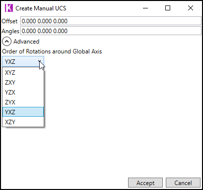
2. Enter user coordinates and choose an order of rotation under the 'Advanced' pull down. The default order of rotation is YXZ.
3. Click the Accept button to apply the new coordinate values.
4. To save your new UCS see the 'Save UCS' section below.
Save UCS
 Saves a UCS to the Project.
1. In the 'User Coordinate System' section of the ribbon, click the 'Save UCS' button 
2. The 'New Project Item' dialog box will appear. Select a Project folder to save to and give your UCS a name.
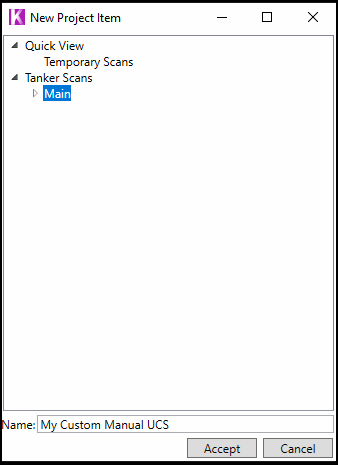
3. Click the 'Accept' button to save your new UCS.
4. The new UCS will now be listed in Project Explorer.
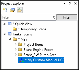
5. Save your Project. Right click on the Project name (Tanker Scans) and choose Save or use the keyboard shortcut (Control+S).
Clear UCS
 Clears an applied UCS
1. In the 'User Coordinate System' section of the ribbon find the 'Clear UCS' button  This will clear a custom UCS and return the Project to its default coordinates.
UCS From Plane
 Creates a UCS that's fitted to a plane in the scan data.
1. Using your mouse and the Point  tool, select a scan point located on a plane in the scan data.
2. Click the 'UCS From Plane' button  to open the 'Create UCS' dialog box.
![]() Note: The 'UCS From Plane' button will be greyed out until a scan point is selected.
Note: The 'UCS From Plane' button will be greyed out until a scan point is selected.
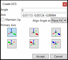
3. Choose 1 of the 6 primary axis and if needed set an angle of rotation. The white sphere shaped handle can be manually rotated while the cube shaped handles can be clicked to adjust the angle in 90 degree increments.
4. Click the Accept button to apply the new coordinate values.
5. To save your UCS see the 'Save UCS' section above.
UCS From 3 Point Plane
 Creates a UCS that's fitted to a plane based on 3 points.
1. Using your mouse and the Point  tool, select your first point. This can be a point in the scan data or somewhere on an object such as a piping component or OBJ file.
2. Click the 'UCS From 3 Point Plane' button  . Using the mouse, click select your next two points. After all 3 points have been chosen the 'Create UCS' dialog box will appear.
3. Choose 1 of the 6 primary axis and if needed set an angle of rotation. The white sphere shaped handle can be manually rotated while the cube shaped handles can be clicked to adjust the angle in 90 degree increments.
4. Click the Accept button to apply the new coordinate values.
5. To save your UCS see the 'Save UCS' section above.
UCS From Object
 Creates a UCS based on an object inside your Project.
Supported object types are Kohera3D Piping components and the Scanner Location of an individual scan.
1.Using your mouse and the Point  tool, either click a scan point in the desired scan to be your UCS object OR select a Kohera3D Piping component for your UCS object.
2. Click the 'UCS From Object' button  in the ribbon.
![]() Note: The 'UCS From Object' button will be greyed out until an object is selected.
Note: The 'UCS From Object' button will be greyed out until an object is selected.
Scanner location as UCS Object
Piping component as UCS Object
UCS From Design Points
 Creates a UCS based on an object's design point.
Supported design point objects are Kohera3D Piping components.
1.Using your mouse and the Point  tool, first click a design point on a piping component in your Project.
2. After clicking the desired design point, choose the 'UCS From Design Points' button  in the ribbon.
![]() Note: The 'UCS From Design Points' button will be greyed out until a design point is selected.
Note: The 'UCS From Design Points' button will be greyed out until a design point is selected.
UCS Context Menu Options
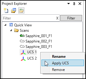
Multiple User Coordinate Systems can be created and saved to a single Project.
Right click a UCS object in Project Explorer to make it Active with 'Apply UCS'. The context menu also allows a user to Rename or Remove it from the Project.
→ See also Transformations
